Libraries
Technical Articles
| Flywheel bolt problem | Disc brake hub and rotor differences |
| Radiators | Wing mirrors |
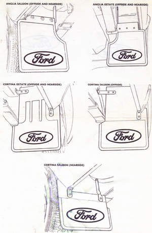
| Original wheel trims | Mudflap mounting |
| Fan blades | Rotor buttons |
|
GDB525
|
GDB520
|
GDB535
|
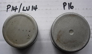
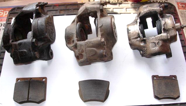
Above is an image showing the 3 different types of brake calipers fitted to the MK1.
From left to right. The P16 fitted to 6/66 on GT and Lotus. Next the P14 as fitted to GT and Lotus prior to 6/66. Then the caliper LU14 fitted to all standard vehicles after 10/64
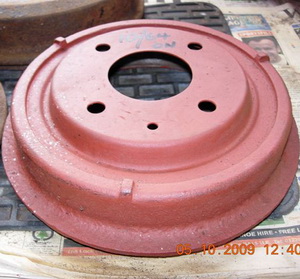 |
This brake drum was fitted on standard car from 10/64 till end of production. The reason for different drums was the difference in length of the half shaft or axle. |
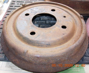 |
This brake drum is fitted to early model standard cars up to 10/64 |
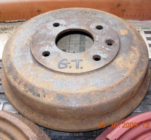 |
This brake drum was fitted to GT and Lotus and can be recognized by its heavy casting. These were used throughout production of the MK1 |
|
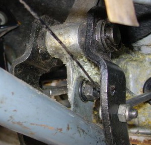
Pre air flow models does not include stoplight switch |
They are lighter in construction with out pedal stop |
|
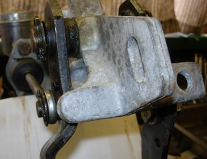
Air flow models have a different pedal shape for clutch also the pedal box is a much beefier construction |
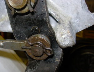
Pushrod also attaches on the opposite side, wavy washer - pushrod - plain washer and finally the 'R' clip |
These images will help you to correctly align master cylinder push rods onto the pedal box for your model. It is very easy to get the orientation wrong.
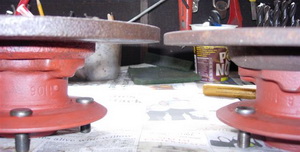 |
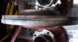
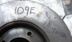
There a 2 hubs and two different sizes of disc rotors. Early GT's and Lotus used 109E-1110 hubs (this is cast in between the two flanges) Notice the wider hub. |
|
|
These use a 3/8" thick disc with the P14 caliper. This was used on cars up to 10/65.
Standard/deluxe and Super airflows used the disc/hub configuration after 10/64 but with a LU14 caliper |
|
|
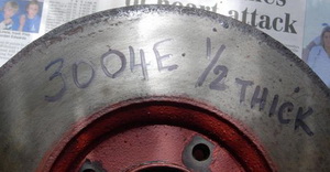
GT's and Lotus after 10/65 used the 3004E/3014E hub with the 1/2" thick disc and the larger P16 caliper, together with the infamous self adjusting rear brakes which were not terribly successful and caused problems during production. Now as can be seen in the pics the later hub is indeed wider (same w/bearings) and this allows the road wheel to clear the caliper as whilst in each case it is possible to fit late discs to early hubs (and vice versa) the wheel will foul the caliper and the thicker disc on the early set up will stop fitment of pads whereas you can successfully use the thinner discs with the P16 hub and caliper.
|
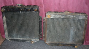 |
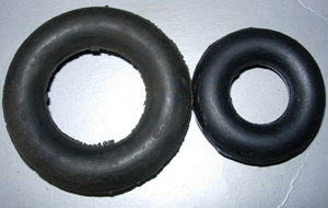
Known as 'bucket radiators' the larger radiator on the left of this picture is for a 1500 engine, while the smaller one on the right is for 1200 engine.
|
|---|
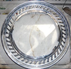 |
The correct wheel trim for a MK1 Cortina (13 inch)
|
|---|---|
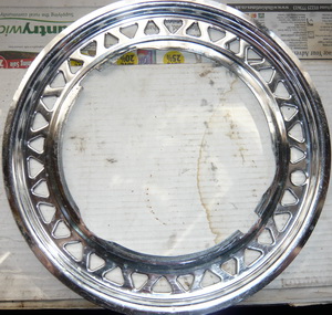 |
While this image is original equipment for a 105E Anglia (13 inch)
|
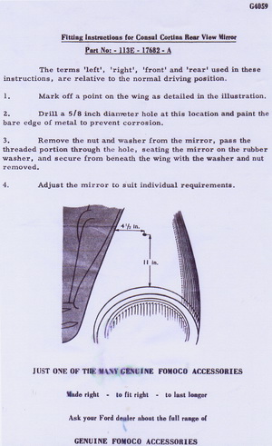 |
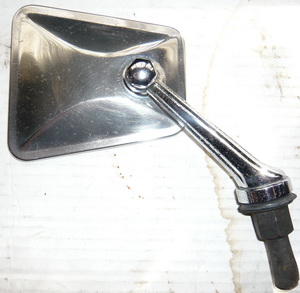
Ford factory instructions for correct fitment on the wing. Above is the original arm and head combination which is still available from Club Spares. Ford had a diff combination for each model and the head is the same as the 105E Anglia but that car had a diff arm. |
|---|
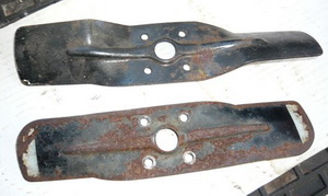 |
The upper fan blade is MK1 part # 109E-8606. the lower fan blade is from a 105E water pump which has been used on the MK1 and corsair
|
|---|
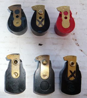 |
Here is an assortment of rotor arms that can be found. Some of these have failed in recent times. The rotor arms with the crosses on them were nearly new and have failed in the last 2 months and it appears similar to a number of condenser failures being experienced some years back. It only 'appears' to effect the rotors with a rivet in them. The red rotor is remanufactured item from Club spares which mimics the last genuine Lucas pattern and is supposed to be the 'bees knees'. Failures accured with 25D4 distributors in different cars.
|
|---|
How To Spot A Real GT
G.T. – Real or fake?
I have been asked a number of times in recent months, how to tell if a G.T. is genuine or not.
There are some easy checks that can be carried out, that should ascertain if the car is what it appears. A conversion could have been carried out some years ago, and of course many cars have been modified over the years, and so be careful before you accuse somebody, of something that they may have no knowledge of.
Please bear in mind also, that the cars are 40 years old, and some things inevitably will have changed; this is a guide to what you could have looked for on a factory fresh car, and you will still have to use a certain amount of personal judgement.
I have not included differences between the 1200 & 1500 version, only what are G.T. specific parts.
Chassis Numbers
These are the same, whether you are dealing with an early or late vehicle.
When you look at the chassis plate located on the inner wing, you will see that it is made up of a series of letters & numbers.
The first two letters denote the place of manufacture for the vehicle.
The two numbers that follow denote that the vehicle type, and will either be:
77 – 2 door G.T. or 78 - 4 door G.T
There are three different types of chassis plate. All pre-airflow cars use a diamond shaped plate, with the plate details engraved into the top surface.
This should be located to the rear of the top suspension mount, near to the bonnet hinge. Very early cars use a plate with three boxes, which then changed to four boxes,
The airflow car uses a rectangular plate, mounted in front of the suspension mount, with the details letter punched upwards, known as reverse stamping.
Log books
Don't worry if the log book does not state 1500 G.T., as it seems to be very rare to find a log book that does have the G.T. letters denoted, even absolutely genuine cars.
Badges
Rear wing badges – look for three clean punched holes in the rear wing, to accept the G.T. shield badge, which will be held in place with either pressed steel nuts, or clips.
Don't worry if the rear panel next to the number plate, has badges for deluxe or 1500, as the Ford factory did not appear to have a direct policy for fitting badges. Again, genuine cars can be fitted with no badge, a deluxe badge, or even a deluxe & 1500 bade.
Dashboard
Late G.T. (Airflow) – Oct ’64 to Nov ‘66
These cars should be relatively simple to check over, as it is very unlikely that somebody would change the main steel dashboard panel.
As the minor instruments sit in a binnacle in the dashboard, remove the two screws holding the clocks in place, and pull forward to reveal the panel behind. This panel should have four semi-circular edges top & bottom; and because the panel was press formed, they should be perfect clean edges. There are also two square holes in the top of the panel, which hold the white plastic screw block.
Whilst the clock binnacle is pulled forward, you will be able to visually inspect the wiring harness, which has equal lighting & connection spurs along its length, and of course be covered in original grey harness tape.
The major clocks are held in a standard plastic binnacle, which should house the rev counter on the left, and the standard speedometer on the right.
Early (Pre-Airflow) – '63 pod rev counter
The very first G.T. used a strip Speedo, which is different to the standard car, in that it reads to 110mph and not as std 100mph. It also features a temperature gauge on the right, and has the warning lamps in different positions, including the ignition warning lamp next to the ignition barrel. The most identifiable feature of this car, is of course the pod rev counter, mounted in a unique casing, attached to the left hand side of the steering column.
Oil and temperature, gauges are mounted into the front of the centre console. The oil pressure gauge being fed by a plastic tube, and is not an electric gauge as on later cars.
Screen wash & wiper switches are separate, and mounted next to each other, to the left of the steering column.
The aluminium trim fitted across the dashboard, should not feature a badge on the glovebox lid section. Deluxe and Super feature their respective script pressed in this piece.
Pre-Airflow – '63/’64 3-dial dash
The interior of the G.T. was face-lifted for a short time, when the std car was fitted with the binnacle and two round gauges. The G.T. was fitted with three round gauges, fitted into the same binnacle. This comprises of a speedometer, a combined fuel, temperature and oil pressure gauge, and a unique rev counter. The rev counter will have the full beam blue warning lamp, fitted to the bottom of the face.
The centre console front panel is plain, as the gauges have moved to the binnacle. The dashboard uses a combined single wiper switch and screenwash pump, mounted to the right of the ignition barrel.
Suspension
There are a number of differences between standard and G.T. suspension, most of which are not easy to notice, unless you know what the part should look like.
Front suspension track control arms
On the standard car these are made of two pressed steel halves welded to together, but on the G.T they are a single piece forging.
However due to the ravages of rust, replacement cast arms were available for the standard car, but they can be differentiated from proper G.T., as the G.T. arm has a flattened section for a bump stop. The bump stop was factory fitted on export models only, by using a different engine crossmember.
Front Struts
The only visual difference between standard & G.T., is the orientation of the spring cup, with the coil spring locates into.
You need to look at the strut as if viewed from the top, with the hub stub axle pointing toward you. Look at the location point for the spring tang in the cup; the G.T. cup will be positioned a 4 o'clock, but the standard will be at 9 o'clock position. The positioning of the cup changes the orientation of the spring, which in turn changes the rate of the spring, i.e. the way in which the spring absorbs the energy through the movement of the suspension.
Springs
Both front & rear springs differ from standard.
The front springs differ in two ways.
· The free length is approximately two inches shorter that the standard, so if you stood the two next to each other, the standard would be much taller. This will give a lower ride height for the front of the car.
· The spring poundage is higher for the G.T. This is the amount of force required to move the spring through a set distance. For example if a spring is 120 Lb/ft, then it requires 120 Lb of load to deflect the spring through one foot of movement. The effect of this is a firmer ride, and less body movement, because of the greater force required to move the suspension.
Rear springs
· Again the spring poundage rate is different.
· Spring height is different, again giving a lowered ride height.
· Late G.T. has an extra leaf added, and so is a five leaf spring.
Rear Axle
Anti-tramp bars are fitted to later G.T. cars. These are located between the axle case & the floor of the rear body. They are used to minimize axle movement under load etc, and consist of welded bars, with rubber bushes fitted into the ends, which are then bolted to the body & axle.
The brackets should be fitted on the body, close to the front of the rear spring, spot welded to the bodywork with a small brazed flange, and not welded.
The driveshaft for all G.T. axles, also feature a thicker flange (where the wheels studs protrude from) than the std car.
The handbrake cable linkage and bracket fitted to the axle casing, also differ to std.
Brakes
Again both front & rear brakes are different to standard as described below.
Callipers
The front callipers on early G.T. were designated P14, later cars P16. If the brake callipers are clean, you should be able to make out the reference number cast into the main body of the calliper; they also have different brake pads and pad pin retention.
The callipers use larger pistons, as well as a different brake pad material and surface area, to increase the braking force that can be applied, and hence increase the stopping ability of the vehicle.
Discs
Front discs for early G.T cars are the same as the standard car; it is only the later G.T. that has a thicker brake disc.
Discs shields
This is the metal shield that fits behind the disc. The G.T. uses a different shield, as the calliper cut-out is larger, so look for evidence that the shaped aperture has been cut and modified.
Rear drum brakes
These are 9" in diameter by 1¾ " wide, but the standard are only 8" in diameter – this is an obvious difference, and so easy to find.
Obviously the brake shoes are different, but I am not getting into trying to tell you how to identify them here.
Wheel cylinders for early G.T., are a large cast body with opposed pistons, and a sliding bar hand brake linkage. This simply pulls in and out to operate the brakes, and does not pivot like a lever.
Later G.T. use a similar cylinder to standard, but it is a different diameter to increase braking force.
Handbrake
All G.T.'s use the dash mounted handbrake lever, situated to the right hand side of the steering column. Because of the different rear brakes, the G.T. uses a unique handbrake cable. A short cable is positioned between the handbrake, and a second lever attached to the steering box.
Steering
The only difference is the steering box itself. This is a different ratio from standard (15:1) and on G.T. is 13:1 ratio which is 3 ¼ turns lock to lock on the steering wheel. The casing of the box itself will have a steel lug attached, which is the pivot point for the dash mounted handbrake lever described above.
Wheels
The steel road wheels are 4.0" width for G.T.
Engine
Cylinder Head
The G.T. cylinder head is easily identified, as it will have two conical tubes protruding from the inlet ports, which have been inserted into specially machined pockets. These are used to support & locate the inlet manifold.
On airflow vehicles; when looking at the thermostat housing section of the head, there will not only be a threaded hole for a temperature sensor, but a second larger threaded hole for a stub tube, which carries the water to the heated inlet manifold.
There will be a casting number of 116E, located beneath the thermostat area of the head.
Both inlet and exhaust valves are of a larger size, but obviously this is not an easy one to determine.
Inlet Manifold
This is a separate aluminium casting, with a rectangular stud pattern for the carburettor. There should also be a support bar that bolts between the inlet manifold and the engine mount, to support the weight of the assembly. Otherwise the inlet manifold will fatigue, and crack at the flange where it bolts to the cylinder head.
Carburettor
All G.T.'s feature a Weber 28/36 DCD carburettor. This number will be stamped along the flange edge, where it bolts to the inlet manifold.
Exhaust Manifold
The G.T. uses a mild steel tubular manifold, known as a four into two into one, as the pipes start as four separate items, then join into two, and finally into one outlet. This outlet should have a flared conical end, and not be a plain round tube.
Exhaust
This can be identified, as it has a cylindrical silencer box approx 18" long, fitting adjacent to the fuel tank, and does not have the upswept front of the std car to meet the manifold, as the front joint is close to the jacking point on the floor.
Distributor
This uses a different vacuum unit, as well as different bob weights for the ignition advance to std. They are identified by the part numbers stamped on the body of the unit.
Oil Pressure units
Pre-airflow cars use a wet line oil pressure guage, and so expect to see a double brass fitting in the engine near to the distributor. One part of this will take the oil pressure pipe to the guage in the car, the other part of this fitting, will have a small low pressure sender (same as a std car) fitted in the end.
Airflow cars use an electrical pressure sender only, which is approx 1 ½” in diameter and 3” in length, and does not also have the smaller low pressure sender, or subsequently a low pressure warning light on the dashboard.
Transmission / Driveline
Gearbox
This exactly the same as the standard 1500 Cortina, there are no differences at all.
Propshaft/differential
This uses a larger diameter flange than std, as does the differential – All MK2 Cortina’s use this larger flange diameter.
Gearshift remote
One of the most obvious features of the G.T., is the use of a remote gearshift linkage. This is a cast iron bolt-on unit, with a short chrome or enamel black gear stick. Of course this will be hidden by the centre console.
Clutch
G.T. uses the same friction plate as the std car, but a stronger spring pressure cover, to cope with the extra power and torque of the engine.
Interior
Seats & Door Panels
If you are viewing a pre-airflow car, then the interior is shared with the std deluxe vehicle, as is G.T. up to September '65; only if it is a late airflow car, does the interior change, and this then becomes the same as the Super interior.
Centre Console
The front of the centre console (ski slope shaped panel), differs between the three variants.
Pre-airflow ’63 pod rev counter, houses the oil pressure and amp meter gauges. This panel uses a centre peg and catch to fit to the main console armature.
Pre-airflow ’63/’64 3-dial dash, is a completely plain panel.
Airflow Oct ’64 – Nov ’66, this has a raised hump in the ski slope panel, and houses a large rectangular ashtray. The panel uses two chrome screws, one either side, to fix to the main centre console armature.
Carpets
All G.T.’s have colour co-ordinated carpet, as per Super variants.
Horns
All G.T. will feature twin horns as per Super.
Body Shell
All G.T. use a heavy duty body shell, which has a thicker sheet metal floor pan – You’ll have fun trying to measure this one!.
As I said, this is a guide; I’m sure I’ve forgotten something, and I know that some of the descriptions of ‘its different to std’ are of little use, unless you know what all of the parts look like in the first place……but at least you now know where to look!
Useful Cortina Links
- World of Cortina
- Cortina Mk1 discussion forum
- Great Lotus Cortina (USA)
- Australian Cortina MK1 site
- Cortina mark one owners club of Australia Inc.
- Lotus Cortina Register
- Cortina MK1 & small Ford 'Free' Classifieds
- Throbnozzle Racing
- Cortina club of Norway
- Swedish Cortina club
- 105 Speed ( Anglia site, but useful parts)
- Ford Anglia 105E Owners Club
- MK2 Cortina O.C.
- Federation of British Historic Vehicle Clubs

